A Study on Heuristic Berthing System Design with Winch and Damper Assistance
Abstract
Vessel maneuvering problem in the harbor area is generating considerable interests in terms of marine cybernetics. In this sense, the vessel is operated and moves at ultimately low or zero speed in shallow water area. So the vessel is usually aided by the cooperation with thrusters, main propulsion system, tugboats and pilots, etc. In this paper, we suggest a new vessel berthing technique using dampers and winches as a solution for excessively complicate and dangerous berthing work. In the proposed berthing method, in order to manipulate the actuators (winches and dampers), a simple and heuristic control strategy is applied for a basic experiment. Finally, experiments are conducted to verify the effectiveness of the proposed automatic vessel berthing strategy based on the heuristic control method.
Keywords:
Vessel, Harbor, Winch, Damper, Heuristic control method1. Introduction
Vessel berthing is widely considered as the most complicated process in the marine control and automation field. One of the reasons is that the hydrodynamic of the vessel considerably changes and its controllability is greatly cut down when the vessel moves from deep to shallow water. Furthermore, by only manipulating the main propellers and thrusters, it is very easy to appear dangerous collisions between the maneuvered vessel and the moored ones due to the unpredictable vessel motion.1)
Various approaches have been hypothesized to solve this issue. Bui and et al. conducted automatic ship berthing by using bow and stern thrusters. The authors introduced a steering motion model of a vessel and identified all of the model parameters.2) An observer based optimal controller was designed to cope with the uncertain ship dynamics and reduce the measurement facilities. Although this seems to be a useful approach, the reduced actuator controllability under low speed conditions have not fully been resolved. In 1994, Hasegawa and Fukutomi applied artificial neural network control strategy on automatic vessel berthing.3) System model of harbor maneuvering of a vessel including tugboat was established. Many attempts have been made by Bui and et al in order to berth the vessel to the harbor by using autonomous tugboats.4,5) In this work, the thrust and direction of each individual tugboat was calculated by applying redistributed pseudo -inverse algorithm which optimized the energy and improved the controllability. Tugboats assisted berthing system is very plausible, but increasing the number of tugboats also increases the berthing costs on the whole. More recent evidence has demonstrated an automatic berthing system with mooring device installed on the upper deck of a ship.6) The key of this method was rope length adjustment by controlling the angular velocity and the torque of hydraulic winch. One of the major drawbacks to this system is that mooring line is a unidirectional actuator, generates force in one direction, provides only pulling force. So the controllability of the ship may not be guaranteed under environmental disturbances.
In this study, the idea is essentially the same as that introduced in with some modifications or extension.7,8) The automatic vessel berthing system is assisted by dampers and winches instead of tugboats. This method is chosen. Because it is one the safest ways to maneuver the vessel to the harbor. The reminder of this paper is structured as follows. In section II, we provide the structure of the berthing system. A simple control strategy is proposed in section III. The experimental set up and results are also presented in this section. Finally, some conclusions are drawn in the last section.
2. System description
For low-speed applications such as ship berthing system, the dynamic equation of motion in the horizontal plane of an unactuated vessel assisted by combination of a pair of dampers and a pair of winches can be written as9)
| (1) |
| (2) |
Where η = [x,y,ψ]T describes the inertial position and the heading angle in the earth-fixed coordinate frame. ν = [u,v,r]T represents the surge, sway and yaw rates of the vessel in the body fixed coordinate frame. R(ψ) used to express the kinematic equation of motion is a rotation matrix in yaw direction,
| (3) |
The system inertia matrix M includes added mass,
| (4) |
where m is the mass of vessel, IZ is the inertia moment about the z-axis of the vessel, describe hydrodynamic added mass. D is the damping matrix,
| (5) |
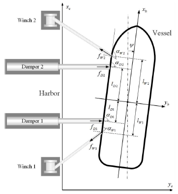
Xu,Yv,Yr,Nv,Nr represent the linear damping coefficients. τ = [τx,τy,τψ] is the control forces in surge and sway directions and yaw moment. In this paper, τ is the result of combined efforts of dampers and winches as shown in Fig. 1.
| (6) |
Where, f = [fD1,fD2,fW1,fW2]T presents pushing forces by dampers and pulling forces by winches.
α = [αD1,αD2,αW1,αW2]T defines the force direction of the dampers and winches.
B(α) is the geometric configuration matrix which captures the relationship between the dampers, the winches and the vessel,
| (7) |
With sα represents sin(α) and cα describes cos(α).
For the first time, dampers and winches are combined to automatically maneuver the vessel to the harbor, the authors want to prove the applicability of this system. Instead of introducing a high level control algorithm for the proposed complex model, we propose a simple berthing strategy in yaw direction. The strategy is actually described and clearly employed in the next chapter.
3. Vessel berthing control strategy
3.1 Experimental apparatus
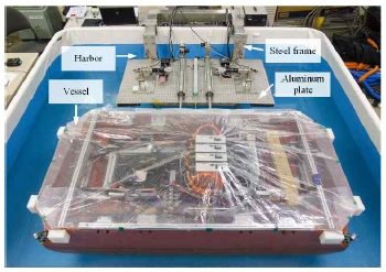
In order to evaluate the efficiency of the proposed controller, the berthing system is set up and tested in the model basin. The experiment was performed in the Marine Cybernetic Laboratory with the vessel model. The motion of vessel is measured and controlled based on LabVIEW program through data acquisition box NI USB-6259. The harbor consists of a steel frame laid outside of the basin and an aluminum plate placed inside the basin. The overview of the vessel berthing system is shown in Fig. 2.
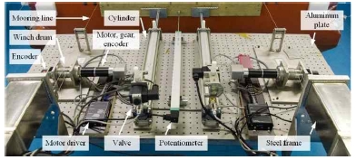
A pair of winch system and a pair of damper system are mounted on the plate as can be seen in Fig. 3. The distance from the vessel to the harbor is measured by the 0.5 m linear potentiometer (GEFRAN) mounted in the middle of this plate.
The rotational angle of two winches is measured by an 1,024 ppr encoder (Autonics) attached on the shaft of winch drum. Each damper system includes a combination of 0.5 m cylinder (SMC), electro pneumatic proportional valve and power amplifier.
The information of each winch system includes a steel winch drum, motor driver (Maxon Escon 50/5) and a combination of DC motor (Maxon), gear and encoder are shown in Table 1.
3.2 Control strategy
In order to cope with high and unpredictable friction characteristics of the cylinders, we propose using pulse force to move the vessel. The motor drives operating in torque mode regularly keep the tension of ropes in an appropriate value determined by the user. When the vessel needs to move, the control program makes a pulling pulse force via motor drivers and decreases the pushing force in a short time via the cylinder drivers, and as a result, the vessel can move.
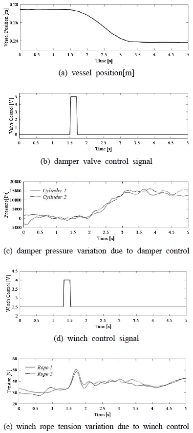
Because the vessel has inertia, after influenced by the pulling force, it takes a short time for the vessel to change its position, so we decide a period of checking time. During berthing process, we check the vessel’s position and compare it with the desired trajectory each period of checking time. As described previously, the object of this study is to move the vessel to the target position by controling two dampers and two winches. Fig. 4 shows an example of using pulse force method to move the vessel. (a) shows vessel’s motion moving to the target position from an initial position. Where (b) and (d) show the control signals for controling the dampers and winches. And (c) and (d) are damper pressure and rope tension variations due to control inputs, respectively. Based on this results, the amplitude and pulse width of control voltage signals to the motor drivers and valve drives as well as the period of checking time are decided by trial and error.
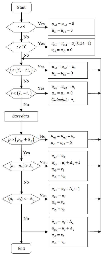
The trajectory for tracking solution of automatic vessel berthing assisted by dampers and winches problem is described by the flow chart as shown in Fig. 5.
The description of all symbol used in the flow chart are shown in Table 2. Notice that the index 1 and 2 in the flowchart represent the forward side and the aft side of the vessel, respectively.
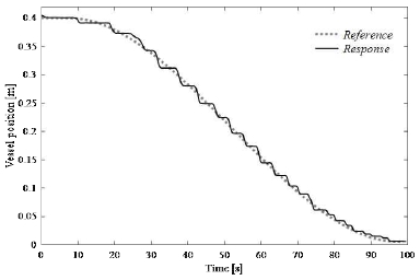
The distance between the ship and the harbor is 0.4 m, the experimental time is 100 s, and the sampling time is 0.025 s.
Based on these conditions, a smooth trajectory is generated.
At the first 5 sec, the control signals to the motor drivers and valve drivers equal to zero. In the next 5 sec, the control program generates ramp signal from zero to a nominal control voltage u0 of 2.5 V to the motor drivers.
Operating in torque mode, the motor drivers keep the tension of ropes at a nominal value of 40 N.
After 10 sec, the berthing process begins. The control program compares the position of the vessel with the desired trajectory. For safety, there is a gap between them. If the position of the vessel is larger than sum of the desired position and an amount of 0.005 m, the control signals to the motor drivers and valve driver are kept at u0 and zero. On the contrary, pulse control signals are sent to the motor drivers to pull the vessel and to valve drivers to reduce the pushing forces, as a result, the vessel can move. The control conditions of the system are that the ship should be berthed while keeping parallel to the harbor, and the angle of the ship attitude should be within the range of ±1 deg in the parallel state to the harbor.
If the ship attitude is out of the set range, it is adjusted by the control program. In Fig. 3, the right part represents the forward side and the left part is the aft side of the vessel. For instance, if the distance from the harbor to the forward side is longer than the aft side, the control program keeps the control output to the left motor driver equal nominal control voltage but creates pulse control signal to the right motor driver.
In the next period, the control program compares the vessel position with the desired trajectory. And if there is no change, the control program increases the amplitude of the pulling pulse to lessen the difference between two side and brings the vessel parallel to the harbor as soon as possible.
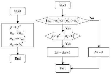
Two small program for data saving and Δu calculating are integrated to the main program to implement this task. The flow charts of the two programs are shown in Fig. 6.
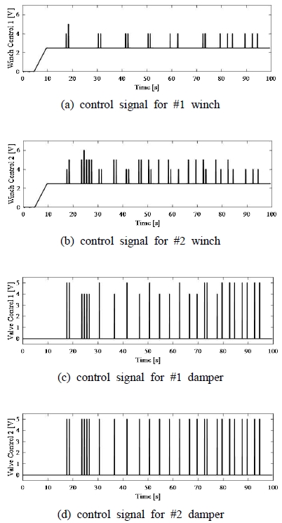
In this situation, the period of checking time is chosen as 1 sec and the pulse width is 0.2 sec. The amplitude of the pulse control signals of the motor drivers and the valve drivers are normally 5 V, however, these amplitudes change depending on status of the system.
3.3 Results
Pulse control signals of winches and dampers during berthing test are shown in Fig. 7.
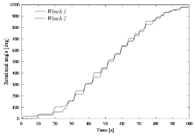
The angles of the forward winch and aft winch are shown in Fig. 8. Notice that, sometimes there are large difference between rotational angles of the forward winch and aft winch. For instance, from 20 sec to 30 sec, the rotational angle of the forward winch is larger than one of the aft, the control program keeps the control signal of forward side winch at the nominal value, but creates pulses and increases amplitude of the aft side winch.
As a result, the vessel is always kept parallel to the harbor during berthing process.
Fig. 9 evaluates the efficiency of the proposed control strategy. It is clearly shown that a good performance is achieved. The control program guarantees that the vessel follows a given trajectory. Based on the berthing results, it is ensured that the vessel can move to the harbor without any collision between the vessel and others located in the harbor as well as between the vessel and the harbor.
4. Conclusions
In this paper, based on analysis of the previous researches, there exist many limits about safety berthing vessel by using rudders and main propellers, thrusters, tugboats or mooring lines. Therefore, we proposed the new berthing approach by combination of dampers and winches. Pulse pulling control strategy are introduced to automatically maneuver the vessel to the harbor without oscillation and overshoot. Experiments are carried out to evaluate the effectiveness of the proposed control strategy. The experimental evaluations show that a good performance for berthing vessel by using dampers and winches can be obtained.
Acknowledgments
This work was supported by a Research Grant of Pukyong National University (2017 Year).
References
-
Y. Zhang, (1997), G. E. Hearn, and P. Sen, "A Multivariable Neural Controller for Automatic Ship Berthing", IEEE Control Systems, 17(4), p31-45.
[https://doi.org/10.1109/37.608535]

- V. P. Bui, J. H. Jeong, Y. B. Kim, and D. W. Kim, (2010), "Optimal Control Design for Automatic Ship Berthing by Using Bow and Stern Thrusters", Journal of Ocean Engineering and Technology, 24(2), p10-17.
- K. Hasegawa, and T. Fukutomi, (1994), "On Harbour Maneuvering and Neural Control System for Berthing with Tug Operation", Proc. of International Conference Maneuvering and Control of Marine Craft (MCMC'94), p197-210.
-
V. P. Bui, H. Kawai, Y. B. Kim, and K. S. Lee, (2011), "A Ship Berthing System Design with Four Tug Boats", Journal of Mechanical Science and Technology, 25(5), p1257-1264.
[https://doi.org/10.1007/s12206-011-0215-4]

-
V. P. Bui, and Y. B. Kim, (2011), "Development of Constrained Control Allocation for Ship Berthing by Using Autonomous Tugboats", International Journal of Control Automation and Systems, 9(6), p1203-1208.
[https://doi.org/10.1007/s12555-011-0622-4]

-
K. U. Yang, J. G. Hur, M. S. Choi, D. J. Yeo, and J. H. Byun, (2017), "Study on Ship Automatic Berthing System with Mooring Lines", China Ocean Engineering, 31(1), p19-29.
[https://doi.org/10.1007/s13344-017-0003-8]

-
A. Tran, S. W. Ji, and Y. B. Kim, (2014), "A Ship Berthing System Design by Cooperating with Tugboats and Dampers", Journal of Drive and Control, 11(3), p7-13.
[https://doi.org/10.7839/ksfc.2014.11.3.007]

-
A. Tran, and Y. B. Kim, (2016), "Dynamics Identification and Robust Control Performance Evaluation of Towing Rope under Rope Length Variation", Journal of the Korean Society for Power System Engineering, 20(2), p58-65.
[https://doi.org/10.9726/kspse.2016.20.2.058]

- T. I. Fossen, (2002), "Marine Control Systems: Guidance, Navigation and Control of Ships, Rigs and Underwater Vehicles", Marine Cybernetics AS, Trondheim.

