A Study on Vessel Motion Control with Towing Ropes and Dampers for Berthing
Abstract
The vessel maneuvering problem in the harbour area is generating considerable interests in terms of marine cybernetics. The vessel is operated by the pilot and moves at ultimately low or zero speed in shallow water area. In this case, the vessel is usually assisted by the cooperation of thrusters, main propulsion system, tugboats and pilots, etc. In this paper, we suggest a new vessel berthing technique using dampers and winches as a solution for complex and dangerous berthing work. In the proposed berthing method, we design the controller to counteract the waves and other effects for guaranteeing the safety during the berthing process. Also, in this paper, experiments are conducted to verify the proposed vessel berthing method and the effectiveness of the designed control system in which unpredictable external force is applied. Finally, the experiment results show that the vessel could approach the defined position in time with effective control action made from designed controller.
Keywords:
Vessel, Tension, Harbour, Berthing system, Winch1. Introduction
Vessel berthing is widely considered as the most complicated process in the marine control and automation field.1-8) A reason is that the hydrodynamic of the vessel considerably changes, and its controllability is greatly cut down when the vessel moves from deep to shallow water. Furthermore, by only manipulating the main propellers and thrusters, it is very easy for dangerous collisions to appear between the maneuvered vessel and the moored ones because of unpredictable vessel motion.4)
Various approaches have been tried to make some solutions about this problem. Bui and et al.5-8) conducted automatic ship berthing by using bow and stern thrusters. The authors introduced a steering motion model of a vessel and identified all of the model parameters.
An observer based optimal controller was designed to cope with the uncertain ship dynamics to obtain desirable control performance by estimating system states. This approach seems to be a useful method, but the reduced actuator controllability under low-speed conditions has not fully been resolved.
In 1994, Hasegawa and Fukutomi suggested an artificial neural network control strategy for automatic vessel berthing.6) However, the conventional methods proposed in this time are kinds of automatic maneuvering technologies or methods which could not give any useful solutions for completing berthing work.
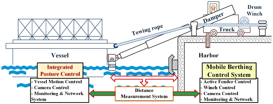
Therefore, the authors propose a new method to complete the final berthing process with preserving working safety. The proposed system configuration is illustrated in Fig. 1. As seen from Fig. 1, the two cylinders and two winch systems are prepared for controlling ship motion. Pulling the vessel by winch with rope and pushing it with damper, we can move the vessel to the final position more safely. It means that the complicate berthing work could be completed by controlling winches and dampers with designed control system9-15) without any supporting system. The effectiveness and usefulness of proposed method are clearly presented by experiment results.
2. Problem Statement
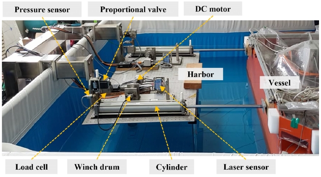
The system proposed and intended for experiment is shown in Fig. 2. The authors use a vessel model to execute the berthing experiment, where two pairs of motor and cylinder are installed in the harbor side.
The proposed idea and system configuration are initialized by considering final berthing condition. The most complicate area (or distance) for berthing may be confined in 10[m] from ship to quay side. In this area, generally, the tugboats and the pilots assistance are needed to occupy safe working process.
The object of this study is to show an easier and safer method than conventional technologies. In the proposed method, any additional assistance system such as tugboat or pilot is not necessary except damper and winch systems installed on the land side. The possibility of the proposed method is presented by following experiment.
As previously mentioned, two pairs of winch and damper cylinder are prepared for controlling ship motion. For starting berthing work, at first, the ends of dampers are attached and the winch ropes are connected to the vessel simultaneously.
After that, the berthing process is started by controlling pulling and pushing forces made from actuators. It means that the desirable control performance and safe berthing work can be achieved by controlling winch and damper systems properly and effectively.
2.1 System description
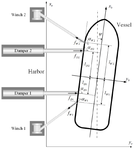
The system configuration of the controlled system illustrated in Fig. 2 is represented as Fig. 3.
Then, let us describe a model of controlled system based on Fig. 3. The dynamic equation of motion in the horizontal plane of the controlled vessel assisted by dampers and winches is written as follows:5,7,8)
| (1) |
| (2) |
η = [x,y,ψ]T describes the inertial position and the heading angle in the earth-fixed coordinate frame. ν = [u,v,r]T represents the surge, sway and yaw rates of the vessel in the body fixed coordinate frame. R(ψ) used to express the kinematic equation of motion is a rotation matrix in yaw direction,
| (3) |
And M is the inertia matrix which includes added mass:
| (4) |
where m is the mass of vessel, IZ is the inertia moment about the z-axis of the vessel, describe hydrodynamic added mass. D is the damping matrix,
| (5) |
Where Xu, Yv, Yr, Nv, Nr represent the linear damping coefficients. τ = [τx,τy,τψ] is the control forces in surge and sway directions and yaw moment. In this paper, τ is the result of combined efforts of dampers and winches as shown in Fig. 1.
| (6) |
Where, f = [fD1,fD2,fW1,fW2]T presents pushing forces by dampers and pulling forces by winches.
α = [αD1,αD2,αW1,αW2]T defines the force direction of the dampers and winches.
B(α) is the geometric configuration matrix which captures the relationship between the dampers, the winches and the vessel,
| (7) |
With sα represents sin(α) and cα describes cos(α).
2.2 Vessel mooring system modeling
Based on the preparation of experiment apparatus, the authors performed the system identification process for describing the dynamic characteristics of vessel berthing system for a half model. Then the dynamic equations of berthing system consisting of pulling and pushing mechanism are represented as follows (i = 1, 2):
| (8) |
| (9) |
Where, Ms (M/2): mass of vessel, bsi: total damping coefficient of vessel, kri: rope stiffness, ysi: displacement of vessel in ye direction, yw: winded rope length from winch. And Jwi, bwi, kwi, Twi, rwi are the inertia moment, damping coefficient, stiffness, torque and radius of winch system, respectively. Using the following relations:
| (10) |
| (11) |
then Eq. (8) and Eq. (9) are represented as follows:
| (12) |
| (13) |
Where,
which are identified by experiment. And, ui = vi is the voltage input to the winch actuator, fi(t,ysi) is assumed as uncertain parts which may not be exactly described or ignored in the model.
Especially, in order to identify the parameters shown in Eq. (13), several experiments have been tried such that one result is illustrated in Fig. 4.
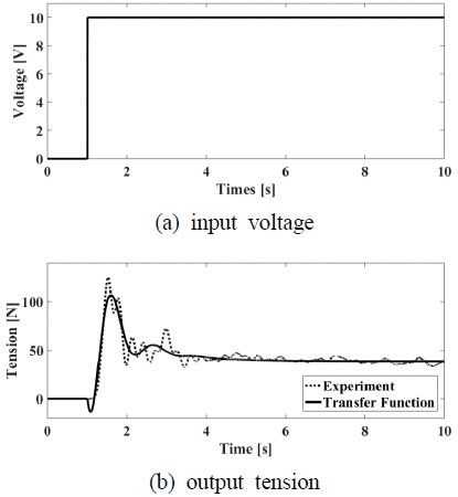
Step response for identifying the system parameters. (a) is the voltage input to the winch actuator(motor). (b) is the tension response
In this case, 10[V] electric power (shown in (a) of Fig. 4) was applied to the winch system such that the rope tension force was obtained as shown in (b) of Fig. 4. In this figure, the dotted line is the tension force of real system get from experiment and the solid line is calculated tension force obtained from a identified model.
Furthermore, using the relations as seen in Eq. (10)~(13), the parameter values are calculated as ai = 132, bi = 2.8, ci = 26.2
2.3 Berthing strategy
We may provide many types of berthing techniques and methods based on the proposed system configuration. In the proposed berthing system, two dampers and two winches are provided and controlled to achieve the given objective.
Here, the authors introduce a considerable simple berthing strategy. It is called a semi-automatic berthing method or technique. In this method, the dampers are manually controlled. On the other hand, the winches are automatically controlled such that the rope tension forces are kept in the defined values. For example, if the damper control valves are closed, the winches rotate and pull the vessel until the tension forces approach the target values. It means that the vessel motion or position depends on the expended length of damper cylinder under the appropriately defined rope tension.
For accomplishing full-automatic berthing system, two actuator system should be actively controlled. However, the semi-automatic berthing method is most friendly one for real working condition and environment. Based on this idea, the authors tried berthing experiment in several times such that the results will be shown in the next chapter.
3. Experiment
3.1 Experimental apparatus
In order to evaluate the usefulness of designed control system, the experimental apparatus is set up and tested in the water basin. The experiment was performed in water basin using a vessel model (weight : 215 kg, length : 2 m, width : 1 m).
The vessel motions are measured and controlled by data acquisition system PCI-6229 (NI) with LabVIEW software.
A pair of winch and damper system is installed on the harbor side. The distance from the vessel to the harbor is measured by the Laser sensor mounted on the plate, the rope tension is measured by Load cell sensor and the cylinder pressure is measured by pressure sensor. All apparatus used for experiment are represented in Fig. 2 and Table 1.
3.2 Controller design
We design a controller based on sliding mode control scheme in order to keep the desired rope tension. Especially, the super-twisting algorithm is introduced for designing sliding mode controller.
Then, a sliding surface is given as follows:
| (14) |
Where mi is positive parameters. The error ei between the desired winch angle θwid and the actual angle θwi is defined as follow:
| (15) |
Taking the derivative time of Eq. (14) gives
| (16) |
From Eq. (14) and Eq. (16), the following Eq. (17) is obtained with a condition of sliding manifold defined as Eq. (18).
| (17) |
| (18) |
In Eq. (17), fi(t,ysi) denotes the uncertain perturbations. The derivative of uncertainty satisfies with the upper bound δi (> 0) of the derivative of the unknown perturbations. And, the control law based on the Super-Twisting Algorithm is calculated as following.
| (19) |
Where
| (20) |
And, the function sign( • ) is defined as follows:
| (21) |
Then, we need to verify the system stability condition with the control law Eq. (19).
By substituting Eq. (19) into Eq. (17), the equivalent sliding manifold is calculated as following.
| (22) |
Where, Ki and Hi are positive control coefficients. Then, the system stability is preserved, if the controller gains satisfy the following conditions:
| (23) |
The stability condition is automatically proved by providing a Lyapunov candidate such that the authors do not illustrate proving process.12-14)
In final, the gains of the winch controller shown in Eq. (20) are chosen as follows:
| (24) |
3.3 Experiment results
The objectives of this study are keeping the target tension of rope and moving the vessel to the desired position simultaneously. Especially, the target rope tension should remain in the defined value throughout entire berthing process.
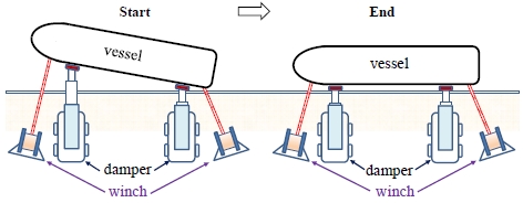
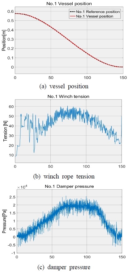
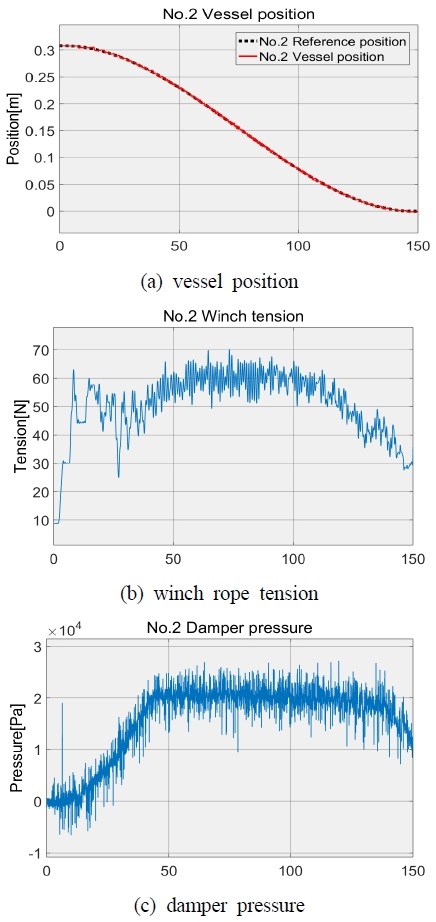
The authors performed experiment by applying the designed controller. The experiment scenario is illustrated in Fig. 5 without any special constraint and with considering real application conditions. At first, we tried a berthing experiment in the nominal condition without disturbance. The results are illustrated in Fig. 6 (bow side) and Fig. 7 (stern side). In the figure, (a) : the vessel position, (b) : rope tension and (c) : damper pressure, respectively. By control the winch and damper system, excellent vessel berthing control performance was achieved as seen in the figures. On the contrary, another experiment was performed by considering some uncertainties.
During vessel moving to the target position, the rope tension should be kept in the defined value as possible as it can in spite of existence of disturbance.
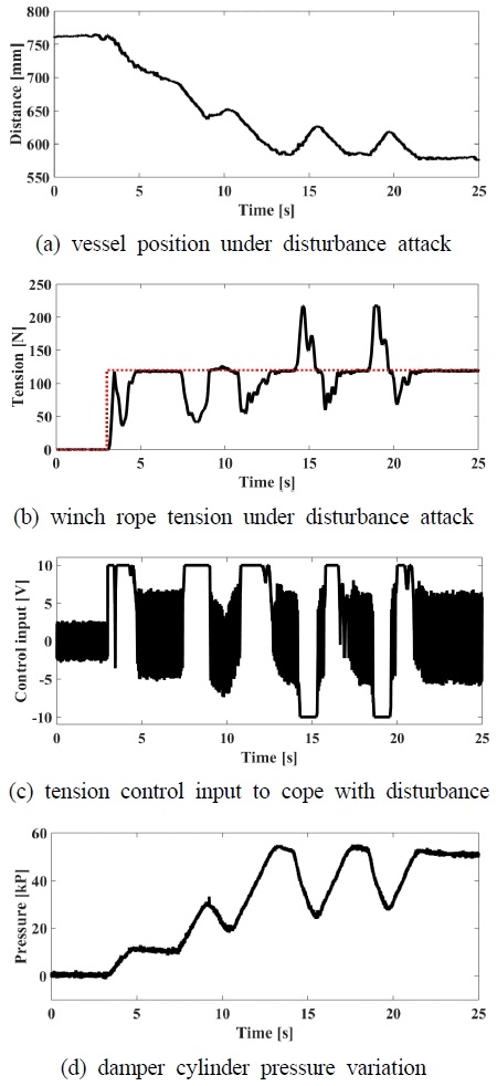
In this case, the target rope tension was set to 120 N which is shown as the red dotted line in (b) of Fig. 8. In Fig. 8, (a) shows vessel position during moving to the final position. While the vessel is approaching the target position (0.57 m), the external disturbance is attacking the vessel in several times. At 3 s, 7 s and 11 s , the vessel was attacked by pushing force toward harbor side. Conversely, at 14 s and 18 s, pulling force attacked the vessel.
With the condition aforementioned, the vessel can approach the final position in 14[s] by controlling two actuators. The controlled vessel motion is illustrated in (a) of Fig. 8. Also, the rope tension and winch control signal are shown in (b) and (c), respectively. (d) of Fig. 8 shows the pressure change of damper cylinder during entire berthing process.
As shown in the experiment results, we can find out that the vessel is well controlled and robustly moves to the final position as intended, regardless of attacking of disturbance.
4. Conclusions
In the conventional berthing technologies or methods, there exist many limits to the safety of berthing operation where rudders, main propellers, thrusters, tugboats and mooring lines are generally provided. The high technologies have been developed and applied to many industry fields. However, the berthing work strongly still depends on human power and stays on the pre-modern technology level.
To overcome primitive berthing method, the authors proposed a new berthing technique/method by combining dampers and winches. The proposed idea was initialised by considering the real working condition. As mentioned before, many working apparatuses for berthing should be prepared in land and sea side of harbour simultaneously. In this study, the authors proposed a new berthing method only using the apparatuses prepared on land side without sea side apparatuses. It is the novelty of this research such that we could obtain numerous advantages. The representative one is reduction of air pollution get from not using tugboats. Except that, it is expected that we find out uncountable side effects by providing the proposed technique.
Author contributions
C. W. Kim; Conceptualization, Formal analysis, Methodology and Writing-review & editing. C. W. Kim and H. C. Park; Validation & editing. Y. B. Kim; Writing-original draft, Project adminstration and Supervision.
References
-
K. H. Kim, B. G. Kim and Y. B. Kim, 2018, "A study on the optimal tracking control system design for automatic ship berthing", Journal of the Korean Society for Power System Engineering, Vol. 22, No. 4, pp. 72-80.
[https://doi.org/10.9726/kspse.2018.22.4.072]

- Y. B. Kim, Y. W. Choi and G. H. Chae, 2006, "A study on the development of automatic ship berthing system", Proceedings of the Korean Society for Power System Engineering Autumn Conference, pp. 419-423.
- Y. B. Kim, Y. W. Choi, J. H. Suh and K. S. Lee, 2006, "A study on the development of the real-time detection technique for automatic ship berthing", Proceedings of the Korean Society for Power System Engineering Spring Conference, pp. 306-313.
-
Y. Zhang, G. E. Hearn and P. Sen, 1997, "A multivariable neural controller for automatic ship berthing", IEEE Control Systems, Vol. 17, No. 2, pp. 31-45.
[https://doi.org/10.1109/37.608535]

- V. P. Bui, J. H. Jeong, Y. B. Kim and D. W. Kim, 2010, "Optimal control design for automatic ship berthing by using bow and stern thrusters", Journal of Ocean Engineering and Technology, Vol. 24, No. 2, pp. 10-17.
- K. Hasegawa, and T. Fukutomi, 1994, "On harbour maneuvering and neural control system for berthing with tug operation", Proceedings of International Conference Maneuvering and Control of Marine Craft, pp. 197-210.
-
V. P. Bui, H. Kawai, Y. B. Kim and K. S. Lee, 2011, "A ship berthing system design with four tug boats", Journal of Mechanical Science and Technology, Vol. 25, No. 5, pp. 1257-1264.
[https://doi.org/10.1007/s12206-011-0215-4]

-
V. P. Bui and Y. B. Kim, 2011, "Development of constrained control allocation for ship berthing by using autonomous tugboats", International Journal of Control Automation and Systems, Vol. 9, No. 6, pp. 1203-1208.
[https://doi.org/10.1007/s12555-011-0622-4]

-
C. Edwards and S. K. Spurgeon, 1998, "Sliding mode control theory and applications", T. J. International Ltd, Padstow, UK. (ISBN:9780748406012)
[https://doi.org/10.1201/9781498701822]

-
S. K. Spurgeon, 2008, "Sliding mode observers: a Survey", International Journal of System Science, Vol. 39, No. 8, pp. 751-764.
[https://doi.org/10.1080/00207720701847638]

-
L. Fridman, J. Moreno and R. Iriarte, 2011, "Sliding modes after the first decade of the 21st century", Springer.
[https://doi.org/10.1007/978-3-642-22164-4]

- J. Rivera1, L. Garcia, C. Mora, J. J. Raygoza and S. Ortega, 2011, Sliding mode control, InTech, India. (ISBN: 978-953-307-162-6)
-
A. Bacciotti and L. Rosier, 2005, "Liapunov functions and stability in control theory", Springer. (ISBN: 978-3-540-21332-1)
[https://doi.org/10.1007/b139028]

-
A. Barth, M. Reichhartinger, J. Reger, M. Horn and K. Wulff, 2015, "Lyapunov-design for a super-twisting sliding-mode controller using the certainty-equivalence principle", International Federation of Automatic Control, Vol. 2015, No. 48-11, pp. 860-865.
[https://doi.org/10.1016/j.ifacol.2015.09.298]

-
J. Davila, L. Fridman, and A. Levant, 2005, "Second-order sliding-mode observer for mechanical systems", IEEE Transactions on Automatic Control, Vol. 50, No. 11, pp. 1785-1789.
[https://doi.org/10.1109/TAC.2005.858636]


